How to Bend a Conduit Offset Around an Obstruction
Place offset marks toward or away from an obstruction, compare angle choices, count the bend budget, and check chart shrink against ideal geometry.
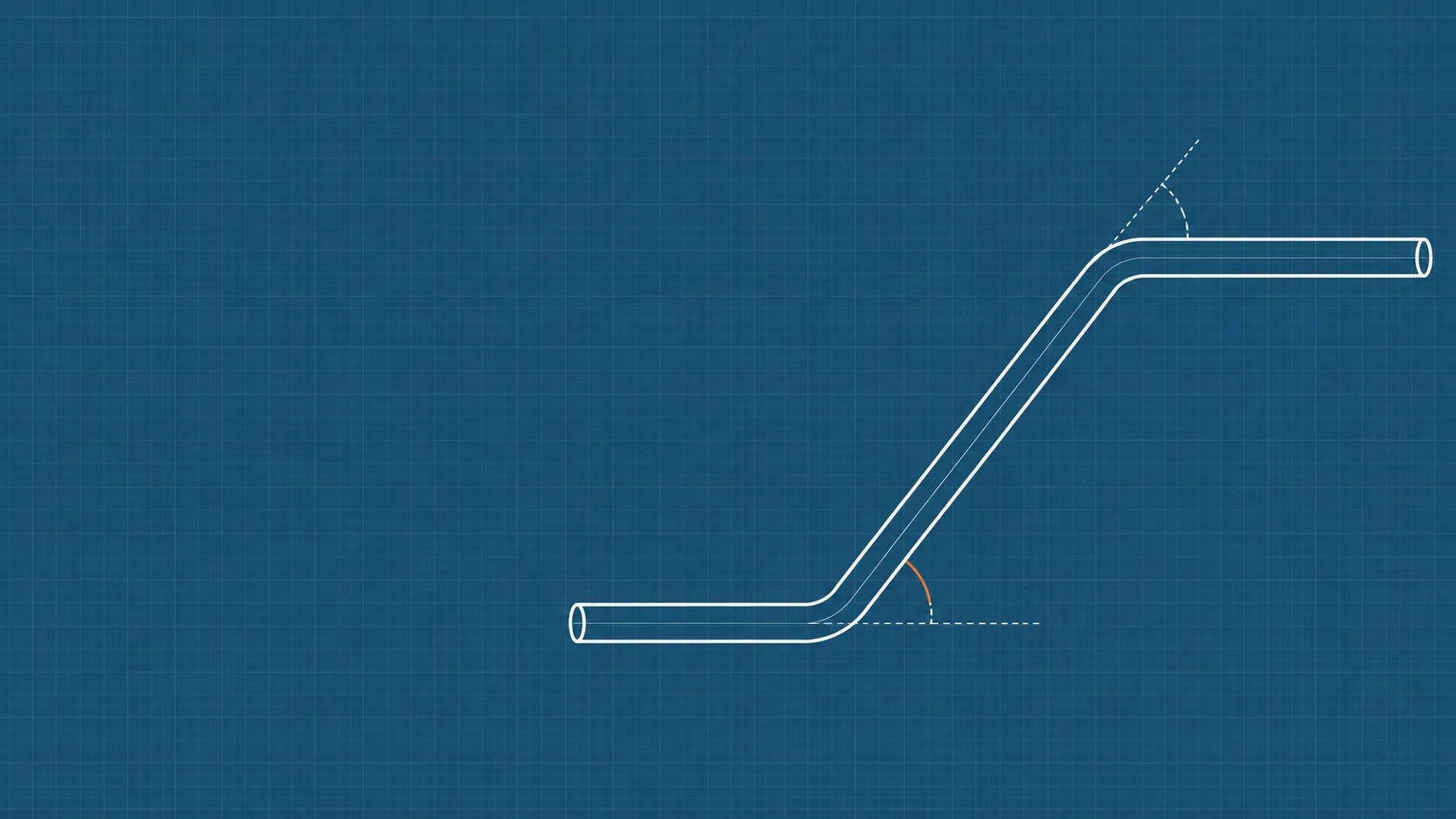
Measure the obstruction height h and its horizontal distance D from your reference, then pick an angle θ; use h as the required perpendicular offset between the conduit legs, allowing for the clearance your route needs. Distance between bends = h × 1/sin θ; when working toward the obstruction, the bend nearest it goes at D + shrink, where shrink = h × tan(θ/2), in ideal sharp-vertex geometry. Use the conduit bend offset calculator for those quantities, then check the placement against the actual obstruction and bender instructions.
Working toward vs away from the obstruction
First identify the approach face of the obstruction and the location where the raised, parallel leg must begin. Here D means the horizontal distance from the fixed reference to that planned bend location, not a measurement along the sloping conduit. Translate the obstruction measurement into that location before marking; an outside-surface clearance measurement is not automatically a centreline offset height.
For the sharp-vertex model, trace the path from the reference toward the obstruction:
- The sloping section occupies a horizontal span h/tanθ.
- The straight section before it therefore occupies D − h/tanθ. If this is negative, the chosen angle cannot fit between the reference and the planned location.
- The sloping section consumes h/sinθ of conduit length.
- Adding the straight and sloping lengths gives (D − h/tanθ) + h/sinθ = D + h·tan(θ/2).
That last term is the shrink allowance. Toward the obstruction, add it to D for the near-obstruction mark, then measure back h/sinθ toward the reference for the other mark. These are theoretical vertices; transfer them to the actual bender marks using its instructions.
Assumed example: h = 4 in, θ = 30°, D = 48 in, with D measured to the intended near-obstruction vertex:
- Shrink = 4 × tan(15°) ≈ 1.0718 in.
- Near-obstruction mark = 48 + 4 × tan(15°) ≈ 49.0718 in, or 49.07 in at two decimal places.
- Bend spacing = 4/sin(30°) = 8.0000 in.
- Other mark = 48 + 4 × tan(15°) − 4/sin(30°) ≈ 41.0718 in, or 41.07 in: measure 8 in back from the near-obstruction mark.
Away from the obstruction, the offset may instead start at a fixed point, such as a box. Keep that start fixed: shrink only changes where the far end lands. For a fixed developed length beyond that start, its horizontal reach is shorter by the shrink; adding shrink to the starting mark would move the very point you intended to hold fixed.
Choosing the angle: space, bend budget and pulling
Assumed example: h = 6 in, with each candidate angle stated below. Lengths are inches, computed at full precision and displayed to four decimal places.
Columns: bend spacing = h/sinθ, horizontal span = h/tanθ, exact shrink = h·tan(θ/2), and budget used = 2θ.
| θ | Spacing (in) | Span (in) | Shrink (in) | Budget |
|---|---|---|---|---|
| 10° | 34.5526 | 34.0277 | 0.5249 | 20° |
| 22.5° | 15.6788 | 14.4853 | 1.1935 | 45° |
| 30° | 12.0000 | 10.3923 | 1.6077 | 60° |
| 45° | 8.4853 | 6.0000 | 2.4853 | 90° |
| 60° | 6.9282 | 3.4641 | 3.4641 | 120° |
A steeper angle makes a shorter offset, but uses more of the bend budget and makes a harder pull. Compare the horizontal span with the space available before the obstruction, then consider the rest of the route. A geometry result does not establish that your particular shoe can make the bends in that space.
Counting offsets against the 360° limit
Article 358.26 (EMT) limits bends between pull points to the equivalent of four quarter bends, 360° total. The same limit appears for RMC in 344.26, IMC in 342.26 and PVC in 352.26. These are designation references, not verification of the final adopted edition; NFPA public development material provides the referenced context. Check the adopted NEC edition and the authority having jurisdiction (AHJ), including the applicable section numbering.
Every offset counts 2θ because both bends count, even though the exit leg is parallel to the entry leg. Assumed example: a 3-point saddle with a 45° centre and equal 22.5° outer bends counts 22.5° + 45° + 22.5° = 90°.
Assumed example: a run has two 90° bends and one 30° offset. Used budget = 2 × 90° + 2 × 30° = 240°. Remaining budget = 360° − 240° = 120°. Each additional 22.5° offset counts 2 × 22.5° = 45°. The quotient 120 ÷ 45 ≈ 2.6667, so 2 more complete offsets fit: 240° + 2 × 45° = 330°, leaving 30°. A third would give 240° + 3 × 45° = 375°, exceeding the limit. Two fit within the budget; they do not fill it exactly.
Budget the whole interval between pull points before selecting the offset angle. An angle total below the limit does not by itself establish that the conductors can be pulled successfully.
Rule-of-thumb shrink vs exact geometry
The chart allowance below is second-hand: commonly published chart values, e.g. Chapman Electric's bending guide. Its current resource page publishes the listed fractions; this is not a verified chart for your particular bender.
Assumed example: h = 10 in, with each angle and chart fraction stated below. The difference is exact shrink minus chart shrink, calculated as 10 × (tan(θ/2) − chart fraction). The exact ratios and differences are rounded to four decimal places only after calculation. * Chart values are second-hand, as noted above.
| θ | Chart (in/in) * | tan(θ/2) | Diff., 10 in (in) |
|---|---|---|---|
| 10° | 1/16 | 0.0875 | 0.2499 |
| 22.5° | 3/16 | 0.1989 | 0.1141 |
| 30° | 1/4 | 0.2679 | 0.1795 |
| 45° | 3/8 | 0.4142 | 0.3921 |
| 60° | 1/2 | 0.5774 | 0.7735 |
A real bend follows an arc of radius R instead of turning at a sharp vertex. For the same tangent lines, the two tangent legs total 2R·tan(θ/2), while the arc length is R·θ, with θ in radians. The arc is therefore shorter by 2R·tan(θ/2) − R·θ per bend. This explains geometrically why a real bend can need less length allowance than the sharp-vertex value; it is not a calibration for a particular tool.
The derivation of any chart cannot be confirmed here. The bender manufacturer's chart and a test bend take priority. Keep the angle and its corresponding chart allowance together; do not infer a radius or springback correction from these differences. Take-up and deduct, if needed for another part of the run, are bender-specific user inputs.
Check the offset before you install it
- Measure the perpendicular offset height between corresponding points on the parallel legs; use the same measurement basis as the planned h.
- Check that both bends are in one plane. Lay the conduit flat on a suitable surface or use a level to compare the legs.
- Confirm that the near-obstruction mark landed where planned relative to the fixed reference and the approach face, with the required clearance.
- If it does not fit, re-bend only as the manufacturer permits or cut a new piece rather than forcing it into place.
Mistakes this workflow prevents
- Measuring D to the far face of the obstruction. The raised leg may then begin too late to clear the approach face.
- Adding shrink to a fixed starting point when working away. Account for the shorter far-end reach while preserving the starting location.
- Omitting offsets from the bend budget. Parallel entry and exit legs do not cancel the bends used between pull points.
- Pairing a chart shrink value with a different angle's multiplier. The resulting height and placement no longer describe the same offset.
This article uses ideal geometry, has not been reviewed by a licensed electrician, and is not a compliance determination. Confirm the layout with the bender manufacturer's instructions, a test bend, the adopted NEC edition and the AHJ.
FAQ
Do I add shrink to the distance to the obstruction?
What changes when I bend away from a box?
Which face of the obstruction should I measure to?
Do offsets count toward the total bends between pull points?
Why is the calculator's shrink larger than my bender chart's allowance?
What should I check if the offset will not fit?
RELATED TOOLS
Data is transcribed from NEC 2023 Chapter 9 into versioned tables, with calculations performed by code. Automated checks cover selected outputs and consistency; not every cell has been independently reviewed. WireFillChart is not affiliated with or endorsed by NFPA. Verify against the code adopted by your local AHJ.